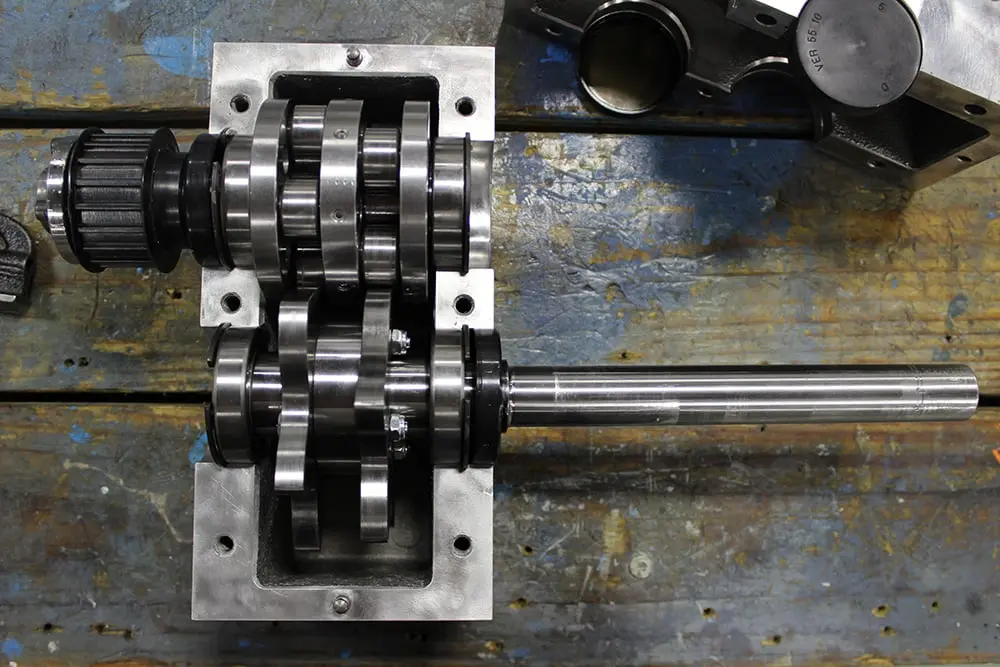



Replacing a CAMCO indexer requires more than matching a model number. Motion Index Drives evaluates the existing mounting dimensions, output height, indexing pattern, cycle time, load requirements and controls to identify a suitable rotary indexer replacement. This guide explains what information engineers should collect to evaluate compatibility and minimize machine modifications.
To replace your CAMCO indexer with a Motion Index Drives Indexer package we will ask for the:
If an original Camco drawing is available, it can be used to verify the Camco indexer is a “Standard” assembly or is a “Special design“ with housing modifications, or some other special detail that would be specific to the application.
The model number is just the first step in determining what size Motion Index Drives indexer package is required to replace a Camco indexer package.
Every Camco indexer is supplied with a name plate attached to the indexer housing where the model number can be found. Camco model numbers give the series of indexer as well as the model size, and the number of stops.
If the name plate is not present, the task of identifying the application and taking measurements of the available space to fit in a Motion Index Drives needs to take place.
In this case, identifying the application parameters and getting the physical dimensions of the available space between bottom of dial plate and top of base is required.
How do I measure the output height of a rotary indexer?
Measuring the output height of a rotary indexer requires taking a measurement from the bottom of the indexer housing feet to the top of the rotating output flange of the indexer, to give us the overall height of the Camco indexer. In some assemblies the reducer would hang below the feet of the indexer, so the indexer would be mounted on risers. In this case, a measurement from the top of the base plate to the bottom of the dial plate will give Motion Index Drives the envelope we have to work with to fit in one of our indexers.
Maintaining the existing output height can help limit modifications to the machine. If the replacement differs in height, MID can evaluate the available space and the mounting arrangement before recommending a configuration.
In order for the indexer to operate within a similar capacity, it also has to physically integrate into the existing machine.
Measurements to provide would be the:
The second step would be to identify the application parameters. This includes the diameter of the dial plate, the number of stations required, weight per station, radius to the CG of the fixture/part, and the index time for one index.
To determine the number of stops on an existing indexer is as simple as counting the number of stations/fixtures on the dial itself.
6 stops = 60° per index
Not every application simply divides 360° equally, particularly when evaluating programmable systems.
Determine the indexing pattern to document exactly how the existing machine needs to move.
Provide the:
Document the cycle time & motion requirements. MID needs to understand how quickly the machine must index, not simply where it needs to stop.
Provide:
Weight alone isn’t enough to properly size an indexer. The distribution of that weight affects inertia and the torque required to accelerate and decelerate the load.
MID will need:
There would not be any advantage to reusing an existing motor. The existing VFD can be reused if it has the correct output voltage required. The existing controls and PLC can be reused going from a Camco to a Motion Index Drives indexer package.
Include information about how the current CAMCO indexer is driven and controlled:
The third step is to take some measurements to determine the available space or envelope the Motion Index Drives indexer package has to fit into the existing machine.
The replacement indexer does not have to have the same dimensions; however, it is beneficial to the end user to have a bolt for bolt direct replacement. A direct replacement will allow the replacement indexer to be installed with zero changes to the existing overall machine. Our priority is maintaining mounting dimensions, output height and existing machine interfaces.
If a Motion Indexer can be supplied with a base plate and subplate that the existing dial would mount to, and still fit into the existing envelope, then it is essentially a direct bolt for bolt replacement with the same dimensions. MID can evaluate the application and recommend the appropriate indexer even if some machine modifications are required.
Whether a replacement can be installed without changes depends on the available envelope, mounting interfaces, output height, and application requirements. Identify any surrounding equipment that cannot be modified during the replacement review.
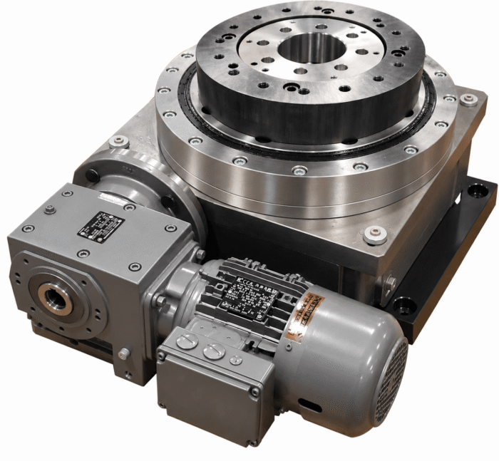
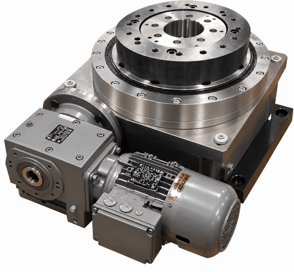
This rotary index table was designed and retrofit by Motion Index Drives with the exact hole pattern to match the existing CAMCO rotary indexer. The top dial and base plateallowed the customer to mount it to their existing machine base without having to redesign any of their machinery at all. Learn more about affordable ways to integrate automation into an existing product line.
| Information | What to Provide |
| CAMCO Identification | Model, serial number and nameplate photo |
| Existing Unit | Photos from multiple angles |
| Mounting | Base and mounting-hole dimensions |
| Output | Output height and output dimensions |
| Index Pattern | Number of stops and index angle |
| Cycle | Index time, dwell time and total cycle time |
| Load | Tooling, dial plate and product weight |
| Tooling | Dial diameter and load distribution |
| Motor | Manufacturer, HP, RPM and voltage |
| Controls | VFD, servo, PLC and sensor information |
| Drawings | Existing machine/indexer drawings if available |
| Operation | Hours/day, shifts and duty cycle |
| Constraints | Areas of the machine that cannot be modified |
After receiving the available information, MID can review the existing equipment and application requirements to identify an appropriate replacement configuration. The review typically follows these steps:
Step 1: Existing Indexer Review
MID reviews the CAMCO model, drawings, photos and dimensions.
Step 2: Application Review
Engineering evaluates load, inertia, cycle time, indexing pattern and duty cycle.
Step 3: Replacement Selection
MID identifies an appropriate rotary index drive and determines what modifications, if any, are required.
Step 4: Integration Review
Mounting, output height, motor, controls and tooling interfaces are reviewed.
Step 5: Replacement Proposal
The customer receives the recommended configuration for the application.
Have an existing CAMCO indexer that needs replacement? Send Motion Index Drives the model information, photos, available drawings, mounting dimensions, indexing requirements, and load details. Our engineering support team can review the application and discuss a suitable replacement configuration. Contact Motion Index Drives to begin your replacement review.